

Why Prototype Sheet Metal Parts Make or Break Your Enclosure Design
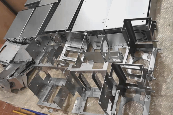
Walk into any hardware startup’s lab, and you’ll see them: 3D-printed enclosures in bright colors, sitting proudly next to bare circuit boards. Walk into any production facility five years later, and those colorful prints are gone. What remains? Sheet metal. Steel. Aluminum. Bent, punched, welded, and finished.
But here’s the uncomfortable truth most prototyping guides ignore: jumping from a plastic 3D-printed shell to a stamped metal enclosure without testing intermediate sheet metal prototypes is like rehearsing a orchestra with kazoos. You’ll miss every real constraint until it’s too late.
This post is about why prototype sheet metal parts aren’t a luxury for medical, automotive, industrial, and telecom devices—they’re the difference between a six-month delay and a first-time-right launch.
The “Plastic Trap” in Device Development
Every device needs an enclosure. And for the past decade, rapid prototyping meant SLA or FDM plastic. Cheap, fast, beautiful. Teams iterate housing designs in days. Then comes the production reality: plastic molds cost $20k–$100k, take 8–12 weeks, and lock you into geometry.
But many devices—especially those handling heat, vibration, RF interference, or structural loads—simply cannot use plastic. Medical diagnostic chassis require EMI shielding. Automotive sensors need thermal dissipation. Industrial controllers demand impact resistance. Telecom radios require grounding surfaces. Enter sheet metal.
Yet most teams prototype sheet metal enclosures only once—at the pre-production pilot stage. That’s the mistake.
Why Sheet Metal Behaves Differently Than Your CAD Model
You can simulate bending springback. You can calculate K-factors. But until you hold a laser-cut, folded, and welded prototype in your hands, you won’t feel:
Tolerance stack in assemblies–Three bends that each flex 0.2mm turn into a 0.6mm gap where a daughterboard should slide.
Hardware interference–Standoffs and PEM nuts don’t align perfectly after welding residual stress distorts the base plate by 1mm over 300mm length.
Cable management chaos–That elegant wire routing slot on screen becomes a sharp burr edge that abrades insulation on the fourth assembly.
Thermal conduction surprises–A heat sink attached to a 1.2mm aluminum panel dissipates heat completely differently than the same sink on 2.0mm steel, yet no thermal sim captures real-world airflow interaction with vent louver shapes.
One medical device company I consulted for designed a portable diagnostic unit with plastic prototypes for 11 months. When they finally cut a sheet metal beta prototype, the power supply’s mounting bracket resonated at 62Hz—exactly the frequency of the internal fan. Cue a full redesign. A $60 sheet metal prototype at month 3 would have caught that.
The Four Critical Roles of Sheet Metal Prototypes
1. Mechanical Verification Beyond FEA
Finite element analysis tells you where stress concentrates—if you input correct boundary conditions. Real prototypes show you where your assumptions were wrong. That bracket that“simulated fine”at 5G vibration? The prototype tears at the notch you thought was decorative.
2. Assembly Process Validation
Sheet metal enclosures are assembled by humans (or robots) in sequences. Prototype parts reveal impossible screw access, interference with pre-assembled components, and the silent killer: dimensional drift across multiple nested parts from different bend cycles.
3. EMC/EMI Shielding Performance
Plastic prototypes with copper tape are theater. Real sheet metal enclosures create conductive paths, ground return planes, and seam gaps. Only a metal prototype lets you measure radiated emissions before tooling. In telecom and automotive, this is non-negotiable.
4. Surface Finish & Corrosion Testing
Powder coating adheres differently to laser-cut edges versus milled surfaces. Galvanic corrosion between dissimilar metals (aluminum chassis + steel screws) shows up in salt spray tests—but only with real material samples.
Low-Volume Reality: When Prototype IS Production
Here’s where most guides get it wrong: for many industries,“prototype”sheet metal parts are the same parts used in low-volume production (500–5,000 units). No hard tooling. No stamping dies. Just laser cutting, CNC bending, and manual welding.
This changes your development mindset entirely. You’re not prototyping toward a future manufacturing method—you’re prototyping with your actual production process. Every design improvement you make on revision 3 of the prototype goes straight into customer-shipped units. Medical devices, analytical instruments, robotics, and defense electronics all follow this model.
Practical Steps: How to Fail Less With Sheet Metal Prototypes
Start week one with a flat pattern. Even before bending, laser-cut a single flat sheet to check hole spacing and board mounts.
Use progressive bend prototypes. Bend one feature→measure→adjust CAD→bend next feature. Never bend all lines on the first try.
Prototype joints and fasteners early. Welding distortion, rivet clearance, and PEM nut seating all require physical samples.
Don’t skip the finish. A raw aluminum prototype hides how powder coating adds 0.1–0.3mm per surface, throwing off slide-fit assemblies.
The Bottom Line
Sheet metal prototype parts are not about“looks like.”They are about“works like.”They reveal the physics your screen cannot show: springback, resonance, distortion, grounding, and the thousand small misalignments that kill production schedules.
For device engineers in medical, auto, industrial, and telecom, the question isn’t“Can we afford sheet metal prototypes?”It’s“Can we afford not to make them?”Because the cost of a bent metal box before tooling is a rounding error. The cost of fixing a bent metal box after shipping 2,000 units is a career event.
So next time your team reaches for another plastic print, stop. Ask: what would a laser-cut, folded, real-metal prototype teach us today? The answer might just save your next product launch.